Verilog 是一種硬體描述語言(Hardware Description Langage, HDL),由於描述與執行方法和軟體不同,所以思考邏輯也不一樣。
基本的設計流程:
- Design Specification
- Algorithmic Model
- RTL Model
- Gate-Level Model
- Switch-Level Model
- Physical Layout
其中的 2 – 5 就會根據我們寫的 Verilog 程式,來合成出對應的電路。一個好的 Coding Style 、以及完善的邏輯,將可以確保電路的正常運作。
RTL Design - A Module
一個電路組即一個模組(Module),使用 Verilog 語言來表現我們想要的邏輯功能。Register-Transfer-Level (RTL),意即利用暫存器(reg)所包含的資料轉移,來達成訊號的 Input/Output (IO),暫存器之間則會有導線(wire)連接。以下是一個 Module 的範例:
1
2
3
4
5
6
7
8
9
10
11
12
13
14
15
16
17
18
19
20
21
22
23
24
25
26
27
module synchronizer(D, Q, clk, rst_n);
input D;
input clk;
input rst_n;
output Q;
reg A1, A2;
assign Q = A2;
always@(posedge clk or negedge rst_n) begin
if(!rst_n) begin
A1 <= 0;
end
else begin
A1 <= D;
end
end
always@(posedge clk or negedge rst_n) begin
if(!rst_n) begin
A2 <= 0;
end
else begin
A2 <= A1;
end
end
endmodule
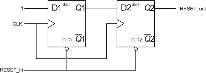
其對應的電路 Block Diagram 是
